IMG_9993_1024x1024.jpg

In this post I will explain how to 3D print and build an illuminated magnifying glass for a Hobby Creek Pana-Hand. The motivation for this project came when I was building my new dual extruder 3D printer (which I used to 3D print the models I will later show) and somehow managed to short out the fan pins and burn an SMD MOSFET. Fortunately for me, I’m not afraid of soldering so I decided to buy a bunch of transistors and go for the kill.

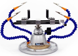
If you’re like me and you haven’t yet mutated a third hand, you will probably find it useful to have some sort of alligator clips stand to facilitate soldering or tinkering$_57.JPG. I currently own a Hobby Creek Pana-Hand which allows me to have not only one extra hand but a gazillion of them ready to obey my every wish and command. I used this setup to get the board in place and position some solder close enough so that I wouldn’t have to hold it, but unfortunately the transistor is really small and I had to use an external illuminated magnifying glass to actually be able to see anything.

After I successfully managed to replace the transistor, my subconscious mind had already made the decision: 2015-11-16_at_14-35-50_1024x1024.jpgI was going to make an illuminated magnifying glass arm! I did some digging through my old junk cupboard and found one of these ubiquitous helping hands with a magnifying glass on it and dismantled the damn thing. The magnifying glass itself is good enough for the kind of soldering I do and it’s about 60mm in diameter which is also quite a decent size.

The final thing I needed which I didn’t already have or couldn’t 3D print was an arm to spare. Fortunately for me Hobby Creek also makes a Universal Holder Arm which looked easy to disassemble so I bought one of those and basically removed the reusable zip-tie and kept the screw.

The Design Process

I followed a pretty inefficient iterative process and ended up with a couple of useless 3D printed parts on the way, but in my defence I’m a software engineer so CAD modelling is not something I’m really experienced at. It is my hope that someone will read this some day and learn something so in this section I will go over the pretty basic electronics, the CAD model design and the selection of 3D printing materials. If you’re not interested in the process I followed to reach the final product, you can go directly to the build section.

Electronics

The electronics of this project are very simple, it is just an LED circuit with 12 LEDs in parallel and a current limiting resistor in series with the supply.  As the name suggests, the current limiting resistor is used to limit the current going through the LEDs and avoid burning them. Due to the parallel arrangement, each LED has the same voltage but, in very simple terms, the current is shared amongst them. The following diagram is a simplification of the final circuit using only two LEDs:

Screenshot from 2016-07-05 21:11:16.png

Now the important part in this circuit is to get the current limiting resistor value right, otherwise we will either risk reducing the lifetime of our LEDs or simply not have enough brightness. The calculation is rather simple, but before we can actually calculate anything we need to find out the following:

  • Voltage source (V_s), which in this case is going to be 5v.
  • Voltage drop of the LEDs (V_l), in this particular case it happened to be 2.8v, but you will have to measure the one of your LEDs. An easy way to do this is to use a high enough resistor (> 1k should be more than enough) and measure the voltage between the LED terminals.
  • Desired LED current (I), we can find this value experimentally by playing with the resistor value and checking if the brightness is enough for our purpose. A rule of thumb with typical 5mm LEDs is to avoid getting too close to 20mA as the LED lifetime will be decreased significantly (Don’t quote me on this). I’ve determined that with about 8mA, the LEDs are bright enough.
  • Number of LEDs you’re going to use (n).

With all this information, it’s now easy enough to calculate the resistor value we need with the following formula:

R=(V_s - V_l) / (I \cdot n)

If you’re too lazy to launch the calculator app on your phone or on your computer, you can always use this online calculator, and go to the parallel case. I must admit I was lazy enough to use this calculator, but in fairness it does provide you with the closest resistor to the value you can actually buy, which is pretty handy. If you weren’t satisfied with my explanation, maybe can help, but I wouldn’t know as I haven’t even looked at it.

If you’re still wondering about the result in this particular case, it’s 22.9Ω but the closest resistor I can buy is 27Ω.  For the power supply I will be using a μUSB breakout board, since I always have a couple of cables lying around the table. The LEDs I will use are standard 5mm white; I also had a couple of 3mm LED, but in my experience those are very easy to damage and the degradation is much faster.

microusb.JPG

Finally a note of caution, I might be wrong on my suggestions so if you want to be 100% sure of what you’re doing, you can probably find other resources online with much more accurate information. In any case, it worked fine for me and if you break a couple of LEDs it’s not the end of the world.

3D Printable Model

Modelling the glass holder as I envisioned it was probably the most difficult part. To create all the models I used Onshape which is a pretty cool 3D CAD modelling software which works pretty well on the browser. The model itself had a couple of requirements such that it should fit the 60mm magnifying glass, the 12, 5mm LEDs and the μUSB breakout board. My original idea was to divide the model in three different parts: the light diffuser, the core and the lid. I started with a very simple prototype which was probably unnecessary and a product of impatience. This prototype only allowed me to fit the LEDs and the magnifying glass, so it was pretty useless.

Prototypes.jpg

The second prototype was another failed idea, but it allowed me to understand how to better design the diffuser since the small diffuser was not very effective. I also figured that connecting all of the LEDs in this approach would not be easy, as I would’ve had to squish the cables around the screws.

The third design worked pretty well on every aspect: the size was just right, the LEDs and the magnifying glass fit really well, the connection between the LEDs was relatively easy to make and the diffuser (which was completely empty) worked pretty well. Unfortunately, at this point I came to the conclusion that white PLA for the diffuser was not the best idea as, even though it diffused pretty well. I believed I could find a better material for the job, and so I did.

The material choice I went for was Clear Taulman T-Glase. T-Glase is very well known for its optical properties so it was the perfect choice for the job. As you can see on the following picture, the light diffusion is quite nice on clear T-Glase:

Diffusion_White_v_Taulman.png

Unfortunately, once I made the decision, I opened a small Pandora’s box of my own. T-Glase is famous for being difficult to print with problems ranging from terrible overhangs, irregular extrusion, flimsy layer adhesion and, to make matters worse, T-Glase has very little adhesion to PLA, so the dual extrusion idea was going to be quite difficult. Fortunately, PLA, the paragon of 3D printing materials, adheres just fine to T-Glase, which solved half of my problems.

Adhesion.png

So once I got past this particular bump on the road, I went ahead and created my next and final design, which included a solid diffuser and a much more compact lid, with the arm connection on the inside. I’ve generated a couple of images from the different parts of the model for your enjoyment:

CAD.png

This final design can be printed on a dual or single extruder 3D printer, although if you go for the single extruder approach you will need to glue the diffuser to the core. The reason for the diffuser being completely solid is because that way I can take full advantage of the internal reflections produced on T-Glase, but if you’re going to use another type of material you might need to print the diffuser hollow. The final STL files can be downloaded here.

3D Print & Build

Bill of Materials

If you want to buy any of the materials I used for this build you can use the following links, although I must warn you that the eBay and Amazon links are “affiliate” links and they provide me with a negligible amount of money.

  • Helping hands or 60mm magnifying glass| eBay UKUS | Amazon UKUS
  • 12 White LEDs | eBay UKUS
  • 2mm x 8mm, Self-Tapping Wood Screws | eBay UKUS
  • Taulman T-Glase Clear | Amazon UKUS
  • PrimaValue Blue PLA | Amazon UK
  • Hobby Creek Universal Holder Arm |
  • μUSB Breakout Board | eBay UKUS
  • 27Ω resistor

With all the decisions made and the models generated, it was time to get on with the 3D print and the build of the illuminated magnifying glass. The first step in the process was to 3D print the models. As mentioned before, I used blue PLA for the core and the lid, and Clear Taulman T-Glase for the diffuser. If you don’t have a dual extruder, you can print each part individually and glue the core to the diffuser with some sort of cyanoacrylate or even hot glue. The settings I used for each material were the following:

Blue PrimaValue PLA:

  • 0.2mm layer height.
  • 185º extruder temperature.
  • 60º heated bed temperature with kapton tape.
  • 50% infill
  • 3 top and bottom layers.
  • 100% cooling fan.
  • 70mm/s speed.
  • 0.4mm nozzle.

Clear Taulman T-Glase:

  • 0.2mm layer height.
  • 238º extruder temperature.
  • 70º heated bed temperature with kapton tape.
  • 50% infill
  • 3 top and bottom layers.
  • 100% cooling fan.
  • 15-25mm/s speed.
  • 0.4mm nozzle.

Since I printed both the core and the diffuser together, I also used a prime pillar which was exclusively printed with T-Glase and an ooze shield printed only with PLA. The reason for this is that the ooze shield, as the name suggests, collects the oozing from both the PLA and the T-Glase (which oozes a lot), and the prime pillar allows to get the T-Glase filament running before printing each layer of the part. I also used a brim to increase the adhesion of both the ooze shield and the prime pillar. You might be wondering why I printed with the diffuser on the bottom, given that it has some overhangs. The main reason for this is that I needed the PLA to be printed on top of the T-Glase as the other way around wouldn’t work due to the terrible adhesion when printing T-Glase on top of PLA. I used Simplify 3D to generate the G-Code and this is the resulting preview:

Screenshot from 2016-07-05 17:56:09.png

Even though the print worked, it was certainly not an easy print. Since Simplify3D doesn’t provide a way to generate different parts of the brim with different materials and the adhesion between T-Glase and PLA is far from perfect, the prime pillar decided to make a run for it, resulting in a mess of spaghetti T-Glase. Fortunately, this madness was contained to the last two layers containing T-Glase. If you think I’m exaggerating have a look (I cleared up some of the mess at this point, but it’s pretty descriptive):

2016-07-05 14.43.11.jpg

Since T-Glase doesn’t adhere to the kapton tape as well as some sources claim, I had to ramp up the temperature to 70º, which ultimately caused the PLA to warp a bit, although I must admit it’s not too bad:

2016-07-05 15.03.17.jpg

Printing the Lid was pretty much straightforward using the settings detailed before. With the printed parts ready, the next step was to add the LEDs and solder them in parallel. To do this, I stripped a cable and introduced it through each groove, finally soldering it to the anode or cathode respectively.

2016-07-05 16.07.18.jpg

Once all the LEDs had been soldered together, I soldered the resistor to the μUSB breakout boar.The positive cable was then soldered to the resistor and the negative cable to the breakout board itself. I also glued the breakout board to the core with some cyanoacrylate:

2016-07-05 17.06.36

The next step was to connect the arm and the lid using the original screw, at this point I must warn you that the screw I received on my Universal Holder Arm might be different to the one you’re using, so it might not be a perfect fit. The fit between the lid and the arm needs to be pretty stiff, with no rotation whatsoever:

2016-07-05 17.08.32.jpg

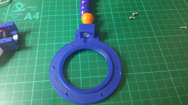
With the lid secured to the arm, it was time to screw it to the core with the 2x8mm self-tapping screws. At this point it is important to make sure that the magnifying glass is already placed on the core, otherwise this will be a futile effort. The end result should look as follows:

2016-07-05 17.10.53.jpg

The final and probably the most exciting step of the process is to connect the arm back to the pana-hand and connect the μUSB cable. If you used similar materials you should get a pretty decent light diffusion all the way to the centre of magnifying glass. In my case, you can see that the light towards the centre is quite uniform:

Conclusion.png

If you used Taulman T-Glase but didn’t manage to get such a uniform light diffusion, you can try printing the part again increasing the nozzle size and reducing the temperature. According to Taulman, this will produce a clearer print with improved optical properties. In any case, I believe that white PLA with a hollow diffuser would have been good enough with sufficiently bright LEDs, so if you try it out yourself, let me know!

Conclusion

Overall I’m pretty happy with the build, sometimes these types of projects end up producing something interesting but with little or no practical use, and probably the same can be said of most of the things I’ve ever 3D printed, but this is definitely one I will make use of. It has also been interesting printing multiple materials as that was the main goal I had in mind when I decided to build a printer with a dual extruder.

Unfortunately printing with multiple materials presents some challenges which need to be overcome by either making a “dual colour friendly” design or making a large number of calibration prints to get the parameters exactly right. In my opinion Simplify3D is probably one of the best slicers out there, but I believe it still needs some work in order to support this type of prints. I could probably come up with a number of additions which would have helped, but the most important one I think would be the ability to print a brim on either the ooze shield or the prime pillar using the extruder assigned to each specific feature.

Creative Commons License
Please be aware that this work is licensed under a Creative Commons Attribution-NonCommercial-ShareAlike 4.0 International License. This includes not only this blog post but also the STL files which I have produced after many hours of work. If you would like to use my work for commercial purposes, please get in contact with me.

That’s all folks!

7580OS_Learning ROS for Robotics Programming - Second EditionAs it can be obvious by now given my posting frequency, writing is not something that comes easy to me, especially not in English, so this will definitely be a surprising post. In August, a couple of friends and I published a book about the Robot Operating System (ROS), a robotics framework which we’ve been using for a long time and which made the basis for the software stack.

This is the second edition of the original Learning ROS for Robotics Programming, which was written by two of the same authors and also reviewed by one of the authors of the second edition. Unfortunately, as life would have it, I couldn’t be involved with the first edition, so I couldn’t pass on the opportunity to participate in this iteration.

This second edition improves upon the first by providing updated content, as the latest versions of ROS are significantly different to those used in the first edition. Be aware that even though the book was originally written to support ROS Hydro, we also provide support for Indigo and Jade in our GitHub repository. We have also improved in general the content of the existing chapters with up-to-date examples and better explanations. Finally, we have replaced the last chapter with two new chapters covering point clouds and robotic arms, which we consider to be a great addition to an already extensive book. The layout of this second edition is as follows:

  • Chapter 1 – Getting Started with ROS Hydro: as the name suggests, this first chapter goes through the installation process of ROS Hydro on Ubuntu, covering also the process of doing so in a VirtualBox virtual machine as well as on a Beaglebone Black.
  • Chapter 2 – ROS Architecture and Concepts: the second chapter covers most of the bits and pieces ROS is made of, including practical examples in which the user will learn how to create nodes and packages that interact with each other, as well as with the famous turtlesim.
  • Chapter 3 – Visualization and Debug Tools: there are many situations in software development where we have to deal with the unexpected, this chapter provides information as to how to use common debugging tools, as well as other tools provided by ROS, in order to debug and visualize our nodes, the data and the interactions between the different elements in our system.
  • Chapter 4 – Using Sensors and Actuators with ROS: a very important part of robotics is dealing with hardware, this chapter covers the usage of common and cheap sensors and actuators supported by ROS, as well as some others more complex, and not as cheap, such as the Kinect or laser rangefinders. Finally, this chapter will also cover how to use an Arduino with ROS to expand our hardware possibilities even further.
  • Chapter 5 – Computer Vision:  from connecting a USB or FireWire camera and publishing images to performing visual odometry with stereo cameras or RGBD sensors, passing through the image pipeline to perform corrections and transformations to our images, this chapter provides an overview of the computer vision tools provided by ROS and OpenCV.
  • Chapter 6 – Point Clouds: this chapter explores a different approach to 3D sensor data communication and processing by using the Point Cloud Library (PCL), which is a library tailored to 3D data (or point clouds) processing and it’s well integrated with the latest versions of ROS, providing message abstractions and other facilities.
  • Chapter 7 – 3D Modelling and Simulation: in many situations, working in robotics requires working without the robots themselves and in some others the amount of tests required to validate a system make it an impossibility to use the robot for that purpose, in those situations the best bet of the roboticist are simulations with accurate 3D models. Since simulations are an indispensable tool for any serious robotics project, this chapter covers the process from creating an accurate 3D model of our robot to simulating it and its environment with Gazebo.
  • Chapter 8 – The Navigation Stack – Robot Setups: this chapter introduces the navigation stack, which is an incredibly powerful set of tools provided by ROS to combine sensor and actuator information to navigate a robot through the world. This introduction goes through the basics of the navigation stack, explains how to understand and create our own transformations and covers odometry with the use of a laser rangefinder or Gazebo.
  • Chapter 9 – The Navigation Stack – Beyond Setups: as a continuation to the previous chapter and using all the concepts explained throughout the book, this chapter finalises the configuration of our robot to make full use of the navigation stack.
  • Chapter 10 – Manipulation with MoveIt!: the final chapter of the book covers the integration between ROS and MoveIt! which provides a set tools to control robotic arms in order to perform manipulation tasks such as grasping, picking and placing, or simple motion planning with inverse kinematics.

The authors of the book, which I consider amongst my best friends and most trusted colleagues, are Enrique Fernández, Ph.D. in Computer Engineering by the University of Las Palmas de Gran Canaria and currently working as a Senior Autonomy Engineer at Clearpath Robotics, Aaron Martínez, M.Sc. in Computer Engineering and co-founder of Subsea Mechatronics, Luis Sánchez, M.Sc. in Electronics and Telecommunications and also co-founder of Subsea Mechatronics, and of course yours truly, M.Sc. in Computer Science and Currently a Software Engineer at Dell SecureWorks (I know, unrelated to robotics).

Come on, stop talking and tell us where we can buy the book…

I know, I know, you’re an impatient bunch, right after this paragraph I’ve included a non-exhaustive list of places where the book is currently sold. If you’re not too sure yet, remember that Christmas is very close and books are always a great gift for friends and family, and who doesn’t want to have a grandma who programs robots* as a hobby instead of knitting?

| | | Barnes&Noble | O’Reilly | Safari Books

We’d like to hear your opinions, so don’t forget to comment if you’ve already read the book or even if you haven’t, and spread the word!

* The authors do not claim this book can teach your grandma to program robots.

It has been a while since my last post and I know that some of you are waiting for some very informative posts about gyroscopes and magnetometers, but today is not that day. I want to talk alogo wee bit about my life in the past few months, since I joined SeeByte and moved to Edinburgh (As you may recall, I was born and raised in Las Palmas de G.C.).

Even though I haven’t written much in this blog, if you go back about a year ago you will see that I was already working on some interesting UUV projects, so SeeByte seemed like the right place for me, since above all I’m a developer/programmer/software engineer/computer scientist. The work I’m doing is very interesting, but unfortunately I’m not allowed to talk about it, suffice it to say it is related to ROVs, as was my , although the level of complexity is much higher.

Three years ago, in 2009, I came to Edinburgh with my sister and thought it would be a great place to live in, and now that I live here I can certainly agree with my past self. If you come from a hot place, like the Canary Islands, the Scottish weather may not agree with you, but I have to say that I really do like the cold, those of you who know me probably know that already. All right, to be fair I sometimes miss the Sun and the heat.

2013-02-18 17.37.10

Aside from my job and my personal life, I have also been dedicating some time to my projects and in doing so I’ve learned quite a lot about electronics. The first of the projects I completed was a GPS datalogger but for that one I will dedicate a full post which is already half written. The rest of the projects are not that interesting but I’m quite proud of two of them, one is a Sound Meter (also known as VU Meter) and the other one is a variable power supply.

The variable power supply uses a few voltage regulators in order to achieve fixed 5v and a variable voltage dependent on the input voltage, which can be anything between 7v and 36v  if I’m not mistaken, and the value of the potentiometer, this voltage can then be set between the input voltage and 1.25v. I also added an LCD voltage meter I bought a while ago from ebay. The end result is a very useful device which I can use to power the rest of my projects with a few standard AA batteries.

2013-02-24 17.32.13

The sound meter was just an idea I had to learn about LED matrices and shift registers, but it ended up being a lot of fun. In this project I also included an Attiny85, which is a very small microcontroller similar to the ones you can find on the . In order to program the Attiny, I used the Arduino itself and the Arduino IDE.

2013-02-23 18.27.50

The basic idea behind the sound meter is to sample the output of a standard microphone and extract from it some sort of volume level. I didn’t want to spend much time with the programming part of the project so the algorithm I implemented is very simple and it is probably not as good as some others you can find on other VU meters.

Once the volume level has been obtained, the shift register is used in order to activate the necessary rows of the LED matrix. In the following video you can see an example of the sound meter working when it was just a prototype on a breadboard, the code I was using is quite different from the latest version and the result is much nicer now, but I was too lazy to make another video.

I think that’s all I wanted to say for now, on my next post I will talk about the GPS Datalogger. Sorry for those who are waiting for the gyro stuff, but you will have to wait a bit more, spoiler alert, gyros are not very useful on their own.

By the way, I’m very disappointed with Google’s decision of killing Google Reader. Please reconsider Google, the options out there aren’t half as good/simple, and that goes for Google+ as well.

One day, looking for cheap sensors on ebay, I found this interesting board which contained everything I was looking for. It basically consists of a 3-axis accelerometer (ADXL345), a 3-axis magnetometer (HMC5883L), a 3-axis gyroscope (L3G4200D) and a barometric pressure sensor (BMP085). My plan is to build an Inertial Measurement Unit (IMU) (or maybe I should call it Attitude and heading reference system (AHRS)) and in the process learn how to interact and interpret the information all of this sensors provide. The fact is I have some experience using IMUs since I used one on my and another one on the , but the fact is they come preprogrammed and there is not much point in working with the raw sensor data unless you want to improve the measurement or give it another use.

For this project I am also using an Arduino Duemilanove, for that reason I wanted to call it ArduIMU, but there is already , so I will have to find another name (suggestions would be appreciated). Connecting the sensor board to the Arduino is pretty straightforward, every sensor has an I²C interface so you can access each of them using the . The drawing was done using fritzing, on which I created the corresponding custom part for this board, although I did something wrong and it does not conform to the fritzing graphic standards.

This will be the first of a series of posts I plan to write about this project, since there are several steps I need to take in order to fully understand each sensor and several more to combine them in order to improve accuracy. In this post I want to talk about the accelerometer and how to obtain the roll and pitch angles from it, which is a process that can also be called tilt sensing.

Accelerometers are devices that are capable of measuring the acceleration they experience relative to free-fall,  the same acceleration living beings feel. As a consequence, accelerometers are incapable of measuring the acceleration of gravity, but can be used to measure the upwards acceleration that counters gravity when at rest. This acceleration is measured as 1g on the z-axis, when both pitch and roll angles are zero, but when the sensor is tilted either the x-axis or the y-axis experiences a component of the upward acceleration, whose magnitude depends on the tilt angle.

Pitch & Roll estimation

Obtaining the pitch and roll angles is then a matter of being able to read the accelerometer, convert these readings to the g unit (1g = 9.8 m/s²), and apply the corresponding equations. The process of obtaining and converting the accelerometer readings depends on the accelerometer you are using, in my case, the ADXL345 in its basic configuration, provides 10-bit resolution for ±2g, but has several other ranges (±2g, ±4g, ±8g, ±16g)  and resolutions (from 10 to 13 bits depending on the range) . Generalizing, the formula used to calculate the acceleration from the accelerometer readings is:

G_{Accel} = Raw_{Accel} \cdot \dfrac{Range}{2^{Resolution - 1}}

Once we have the correct acceleration components, we can proceed to calculate the different angles using the following equations:

pitch = \arctan{\left(\dfrac{G_y}{\sqrt{G_{x}^2 + G_{z}^2}}\right)}     roll =\arctan{\left( \dfrac{-G_x}{ G_{z}}\right)}

For more information about where these equations come from, you can read the documentation I include at the end of this post. As you can see, the denominator of the pitch equation is defined to be always positive, so the equation itself only provides [-90, 90] range, which is exactly what is expected for the pitch angle. In contrast, the roll equation provides [-180, 180] range. It is important to take into account that when the pitch angle is 90º, the surge axis (roll) is directly aligned with the gravity vector, thus we cannot measure the roll angle anymore, this is what is called Gimbal Lock.

Also, be aware that the roll equation is undefined when both G_x and G_z are equal to zero, and that for each possible value of the calculation done inside the arctan function there are two valid solutions, not only on the roll but also on the pitch equation. These problems can be easily solved in code by using the function atan2, which eliminates the angle calculation ambiguity by taking into account the quadrant.

Removing short-term fluctuations using a Low-Pass filter

At this point we already have a fully functional pitch & roll estimation system, but if we experiment with it we will discover that the readings fluctuate quite a bit and this may be very annoying for some applications. Removing these short-term fluctuations can be achieved by means of what is called a Low-Pass filter. This type of filter attenuates the higher frequencies of the signal, thus providing a smoother reading. The Low-Pass filter is easily implemented by using the following equation:

y_{t} = \alpha \cdot x_{t} + (1 - \alpha) \cdot y_{t - 1}

Where y_t is our filtered signal, y_{t-1} the previous filtered signal, x_t the accelerometer reading and \alpha the smoothing factor. It probably may seem obvious, but filtering should be done to the accelerometer readings before calculating the angles, instead of to the angles themselves. Regarding the smoothing factor, the lower we set it, the more it will take for the angle to stabilize, so we should not set it too low because then we could lose real-time behaviour. With this I mean that the reading will not correspond to the real angle until it stabilizes, and this could take some time.

The source code & the ADXL345 library

I developed a small library to interface with the accelerometer, even though at the moment I have only implemented the basic functionality, I plan on supporting all of the device features. You can find it in my github account, where you can also find the processing code I used for the video example below. Thanks to the library, the code is pretty straightforward. It just reads the sensor accelerations which are already converted into gs by the library, applies the Low-Pass filter and then uses the roll and pitch equations to calculate the angles.

#include 
#include 

const float alpha = 0.5;

double fXg = 0;
double fYg = 0;
double fZg = 0;

ADXL345 acc;

void setup()
{
        acc.begin();
        Serial.begin(9600);
        delay(100);
}

void loop()
{
        double pitch, roll, Xg, Yg, Zg;
        acc.read(&Xg, &Yg, &Zg);

        //Low Pass Filter
        fXg = Xg * alpha + (fXg * (1.0 - alpha));
        fYg = Yg * alpha + (fYg * (1.0 - alpha));
        fZg = Zg * alpha + (fZg * (1.0 - alpha));

        //Roll & Pitch Equations
        roll  = (atan2(-fYg, fZg)*180.0)/M_PI;
        pitch = (atan2(fXg, sqrt(fYg*fYg + fZg*fZg))*180.0)/M_PI;

        Serial.print(pitch);
        Serial.print(":");
        Serial.println(roll);

        delay(10);
}

The result

For a more interactive visualization of the data, I also developed an example using processing, which consists on a rotating 3D cube. You can see the results in the following video.

In the next post about my Arduino IMU, I will talk about how gyroscopes work and how to interpret the information they provide.

I finally did it, oficially I am now M.Sc. in Computer Science. After long years of very hard work and sleepless nights, but also living under the comfortable feeling of being always busy and the certainty of what was to come. But that’s it, this moment had to come and my days as a university student are over, but I believe I’m ready for what lies ahead.

My Master Thesis consisted in the design and development of a software architecture for monitoring and controlling a remotely operated underwater vehicle (ROV). It consisted of two software blocks: the control system  and the operation system. The control system is the main software architecture, designed to allow multiple modules to work in parallel connected with one another, each of them controlled by a supervisor which guarantees that the system is always working and deals with software and hardware errors. On the other hand, the operation system allows the user to connect to the control system, visualize the sensory data and operate the vehicle.

The software itself is not very complex, but the design of the architecture is focused on offering efficiency, robustness, reliability and flexibility. One of the main goals of the design is to give the developer the ability of adapting the software architecture to different control models, and even to different types of vehicles or robotic systems, such as an autonomous underwater vehicle (AUV). You can read more about it in the documentation, although it is in Spanish.

I had to give a presentation, where I explained the different aspects of the project and demonstrated the results. It went quite well, and I think it took a little bit longer than expected, but I was finally given the highest grade. Overall, I am certainly going to miss being a university student.

AVORA and the SAUC-E’12 Challenge

As you may already know, I was involved in the construction of an autonomous underwater vehicle (AUV) for participating at the Students AUV Challenge – Europe, which was held in La Spezia (Italy), at the Centre for Maritime Research & Experimentation, from July 6 to 13. It was a great experience being surrounded by top students from all over Europe and Canada, sharing ideas, conceptions and visions about underwater vehicles and robotics.

The sea basin was divided in two equal arenas, this way at most two teams could be working at the same time. The visibility conditions were quite rough and the water currents at the surface were noticeable. The organization provided us with two different workspaces, one on the outside, beside the competition arena, and the other one inside a warehouse. The combination of heat and humidity made it quite complicated to work, even though we were provided with several fans.

The first 5 days were allocated for practice runs, but the truth is some of the teams used this time to finish the construction of their vehicles, including us. On our first few days we did some recordings with an underwater camera, which we used fine grain our detection algorithms. We also finished the construction and did some preliminary tests in the pools. Unfortunately, when everything was ready, the vehicle suffered some leakage  because of an incorrectly sealed connector, which made us lose more than a day cleaning everything, but at least none of the electronic components were damaged.

After repairing the damage, we repeated the tests and verified that everything was working as expected. During these days, the qualification period started, so we were now running against the clock. When everything was ready again, we proceeded to adjust the navigation algorithms directly in the competition arena, something which took longer than expected because one of the arenas was being used for the qualification rounds. The last day of the qualification rounds, we did some simulations of the qualification mission and finished programming it, but at the end, since we had not done enough tests of the mission, we decided not to put at risk the vehicle and gave up our qualification slot.

We all felt a little bit demoralized because of not being able to qualify, but not everything was lost, we still had our chance on the “Impress the judges” category, and we sure came prepared for this one. A while ago, working on our AUV, a member of the team brought a pair of “virtual reality” glasses that he used on . These glasses had attached an external inertial measurement unit, so that the computer could be aware of the operator’s head motion. Since our vehicle was equipped with a pan-tilt camera system, we developed software that combined the camera and the pan-tilt system with the glasses and the gyroscope, so that the user could look around and see the surroundings of the vehicle.

The judges were quite impressed with our telepresence system and it was kind of fun to see them taking turns to try the glasses. They were also quite interested in some of our innovations, such as our pan-tilt camera system or the use of a bend sensor for water velocity measurement. The award ceremony was kind of a surprise, we won the first prize at the “Impress the judges” category, which was much more than we expected after four months work, competing against teams with years of experience and very mature vehicles. After the award ceremony we had a small good-bye party at Lerici, which was shorter than expected, for some of us at least, because of transportation issues.

During these days I had the opportunity to meet some of the most incredible vehicles I have ever seen, not only because of their design, but because of the fact that they were built by students. The vehicle I liked the most was the Canadian one, from the Team SONIA, with a robust and flexible design and an . The team was very prepared and it felt like they had every situation under control, which is a demonstration of their years of experience participating at the RoboSub Competition. Suffice it to say they won this year’s SAUC-E and got third place at RoboSub, quite a feat!

I was also impressed by the design of the vehicle SMART-E, from the University of Luebeck, even though I think it might present a painful challenge for autonomous navigation. This vehicle was shaped like a UFO, and was equipped with 3 thrusters each of which had an additional rotational axis so as to achieve vertical motion. The main hull was transparent, so they took advantage of this to build a strobe light, which was a requirement of the competition, using LEDs all around it. This combined with its shape, made it look like a real UFO, or should I say UCO? (Unidentified Cruising Object).

Overall, it was a worthwhile experience, not only competing but also building an autonomous underwater vehicle from scratch, and I surely recommend it to any student. It is an opportunity to gain more knowledge and to test the knowledge you already have, but more importantly to achieve experience in a real life project.

You can read more about our vehicle on our Journal Paper, or visit or the , or visit the .

Avora AUV SAUC-E’12

Recently, I have been working on a very interesting project, consisting in the design and development of an Autonomous Underwater Vehicle (AUV) for participating in the Students AUV Challenge – Europe held in La Spezia (Italy) at NATO Undersea Research Centre (NURC). We are a team composed of 8 students from different areas (Computer Science, Telecommunications, Electronics, Naval Engineering), in which I have the great honor of being the team leader and lead developer. The name of the AUV (and the team) is AVORA, which means Autonomous Vehicle for Operation and Research in Aquatic Environments, it was intentionally picked as a reference to an ancient deity from the Canary Islands.

The goal of the competition is to perform a series of tasks autonomously, without external information sources and within a fixed time frame, although this time frame is sufficiently large. Taking into account the broad spectrum of missions an AUV can accomplish, we can see that each of the tasks tries to emulate situations that arise in real life, in a limited fashion. The tasks are:

  1. Passing through a validation gate constructed of 2 orange buoys on a rope, 4 meters apart.
  2. Performing an underwater structure inspection. This underwater structure is basically a pipeline of cylinders.
  3. Searching and informing another autonomous vehicle about a mid-water target.
  4. Surveying a wall.
  5. Tracking and following a moving ASV.
  6. Surfacing in the surface zone.
  7. Impressing the judges! In this task, the teams are encouraged to be creative and demonstrate interesting features about their vehicles.

As one can see, completing all of these tasks requires certain type of sensors such as a sonar, cameras, depth and pressure sensors, inertial measurement units, etc, and also a great amount of hard work and time. Our AUV is on its way, since it is our first time, the vehicle has to be constructed from the ground up and it is not an easy job preventing water from getting inside everything.

Another problem with not having the vehicle constructed from the beginning is that most of the work has to be done with each sensor alone and that artificial datasets have to be created in order to fine tune the algorithms. Some of the algorithms require large amounts of data so as to validate them, in such cases we are trying to use datasets provided by others, non-related to the competition. But as I say, being the first time it’s difficult to know what to expect.

From now on I will try to post regularly about our progress. Wish us luck!